
What Is a PA Module?
A PA module (power amplifier module) increases the power of a signal. In radio-frequency engineering, an RF PA module amplifies an RF signal to the level needed by a transmitter or another RF system. It is different from an audio power amplifier: an RF PA is specified for an operating frequency range and RF performance requirements.
When choosing an RF power amplifier, check its frequency range, output power (CW or peak), gain, input drive level, supply voltage, linearity and thermal design. The correct combination depends on the application and operating conditions.
For available configurations, explore our RF power amplifier modules. You can also contact our team with your frequency, output power and integration requirements.
An RF power amplifier (PA) module increases the power of a radio-frequency signal before it is delivered to the next stage or antenna. It is used when the signal source cannot provide the output level required by the system. The right module depends on frequency, output power, signal format, supply capacity and cooling—not output power alone.
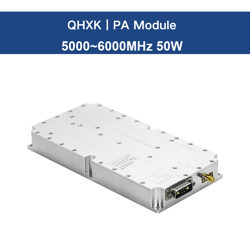
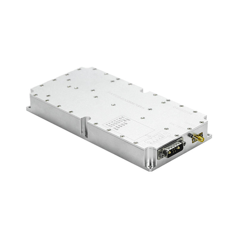
What an RF power amplifier module does
A PA module is the power-amplification stage in a transmitter. It accepts an RF input, increases its power and sends the amplified signal to the next stage or antenna. It does not create the information carried by the signal; it amplifies the existing RF waveform.
Depending on the design, an RF PA module may contain an active gain device, input and output matching networks, bias circuitry, control or protection functions, and a thermal path to the mounting surface. These elements work together to deliver the specified RF performance within the manufacturer’s electrical and thermal limits.
Typical specifications include frequency range, rated or saturated output power, gain, gain flatness, input drive level, linearity, efficiency, supply voltage, current consumption, RF impedance and thermal limits. These values should be read together because a module may not meet every specification at every frequency or operating condition.
How the RF signal path works
A basic transmitter chain is signal source → driver stage, if required → PA module → filtering and antenna system. The source sets the signal frequency and modulation. The amplifier raises the signal power, while filters, cables, connectors and the antenna affect the power ultimately delivered to the antenna.
Excessive input drive can push an amplifier into compression and increase distortion. A poor impedance match can reduce delivered power and may increase stress on the output stage. Follow the manufacturer’s datasheet for input level, load impedance, enable sequencing and protection requirements.
Key RF power amplifier specifications explained
Frequency range and bandwidth
The complete operating band must fall within the module’s specified range. A module designed for 5.0–6.0 GHz is a microwave RF product, not a VHF amplifier. Also check gain flatness and output-power variation across the band rather than relying only on the frequency endpoints.
Output power, P1dB and saturated power
Output power is commonly given in watts or dBm. Check whether a datasheet specifies a rated linear output level, output power at the 1 dB compression point (P1dB), or saturated output power (Psat). These terms describe different operating conditions and should not be treated as interchangeable. Confirm whether the rating applies to continuous-wave (CW), pulsed or modulated signals. For a detailed comparison, see RF power amplifier P1dB vs. Psat.
Gain and gain flatness
Gain, expressed in decibels (dB), describes the ratio between output and input power under stated conditions. Gain flatness describes how much that gain varies across the operating band. Do not confuse dB with dBi: dBi is commonly used to express antenna gain relative to an isotropic radiator, not the power gain of an amplifier module. See also our guide to RF power amplifier gain, flatness and frequency response.
Linearity and signal quality
For modulated signals, evaluate the linearity requirements of the application. Depending on the waveform, useful measurements may include EVM, ACPR/ACLR and spurious emissions. A datasheet’s gain or maximum-power figure alone does not establish modulation quality or regulatory compliance. Our guide to RF amplifier linearity: AM-AM, AM-PM, ACLR and EVM explains these measurements in more detail.
Efficiency, supply and cooling
Confirm the DC voltage range and current capacity, including startup behavior and cable losses. Check whether the efficiency figure is drain efficiency or power-added efficiency (PAE), and note the frequency, output level and signal conditions used for the measurement. Some input power becomes heat rather than RF output, so mounting flatness, thermal interface material, heatsink capacity and airflow all affect continuous operation. Use the manufacturer’s thermal limits and derating guidance. For calculation examples, see RF power amplifier PAE and drain efficiency; for cooling considerations, read the RF power amplifier thermal design guide.
RF matching and interfaces
Review input and output return loss or VSWR, reference impedance, connector type, pinout and mechanical dimensions. These details affect how the module connects to the rest of the RF chain. Confirm the actual interface drawing and operating limits before integration. For more on matching terminology, see RF amplifier VSWR, return loss and impedance matching.
Example: 5000–6000 MHz, 50 W
A system using a 5000–6000 MHz, 50 W PA needs a module whose specified frequency range covers the application. Before integration, verify the current datasheet for gain, supply voltage, connector type, input drive, duty cycle and cooling. The product name alone is not sufficient to confirm these details.
View the 5000–6000 MHz, 50 W RF power amplifier.
How to evaluate an RF PA module
- Define the full frequency range and required output level.
- Specify signal type, bandwidth and linearity requirements.
- Match gain and input drive to the RF source.
- Check voltage, current, enable control and protection.
- Plan thermal management for the real duty cycle and ambient temperature.
- Confirm RF connectors, impedance, dimensions and mounting.
- Compare datasheet values only when their test conditions are equivalent.
For a step-by-step selection process, read our RF power amplifier selection guide. For a discussion of bandwidth trade-offs, see wideband vs. narrowband RF power amplifiers. To interpret individual ratings, use our RF power amplifier datasheet guide, and see how to test an RF power amplifier for measurement considerations.
Frequently asked questions
Is an RF PA module the same as an audio amplifier?
No. An RF PA handles radio-frequency signals used in transmission. An audio amplifier operates over audio frequencies and is designed for audio loads.
Does more output power always mean longer range?
No. Range also depends on antenna characteristics, cable losses, receiver sensitivity, propagation, interference and applicable legal limits. Output power is only one part of a complete link budget.
Does an RF PA module need a heatsink?
Many power modules require a suitable heatsink or other cooling arrangement. Follow the module’s thermal specifications, especially for continuous operation.
Explore RF power amplifier modules
Browse the QHXK RF power amplifier module range to review available product models. For GaN-based designs, see our GaN RF power amplifier module overview.
For selection support, share your frequency range, required output power, signal type, supply conditions, cooling limits and interface requirements through the QHXK contact page. Confirm that the intended operation complies with applicable spectrum, safety and export-control requirements.